


Field guide for research labs • Compact manual metallographic cutting machine selection
How to Choose a Compact Manual Metallographic Cut-Off Machine for Research Labs (When Space Is Limited)
Universities and R&D institutes often face the same dilemma: the lab bench is crowded, operators change frequently, and sample damage is expensive. The right compact manual cutter should reduce heat-affected deformation, keep cut faces consistent, and remain simple enough for daily use—without demanding a dedicated room.
Who this guide is for (and why compact matters)
In a research environment, a metallographic cut-off machine is rarely “just a cutting tool.” It is the first gate that determines whether downstream grinding, polishing, and microscopy will be stable or constantly questioned. A compact manual metallographic cutting machine is especially valuable in shared labs where:
- Space is constrained (crowded benches, limited exhaust routing, tight safety zones).
- Operator skill varies (students rotate; staff time for training is limited).
- Specimens are sensitive (thin sections, heat-sensitive alloys, coated systems, ceramic-metal joints).
Practical benchmark: In many academic labs, specimen rework due to poor cutting (burning, micro-cracks, edge chipping) can consume 15–30% of sample-prep time across a semester. Reducing cut-induced defects is often the fastest path to better metallographic data consistency.
Selection logic: prioritize three risks, not ten features
When labs compare compact cutters, the discussion often gets lost in motor power and wheel diameter. For research reliability, the decision is usually driven by three risks:
Risk #1: Thermal damage (burning, tempering, phase changes)
Cutting heat can create a misleading microstructure—especially in hardened steels, Ni-based alloys, and coated systems. A strong cooling approach is not optional; it is the control knob for microstructural credibility.
Risk #2: Mechanical damage (edge chipping, cracking, delamination)
Brittle materials (ceramics, cermets) and layered composites respond poorly to aggressive feed. A stable manual feed with controllable pressure helps prevent sudden fracture and preserves true edges.
Risk #3: Human variability (training load and repeatability)
In teaching labs, the best machine is the one that produces acceptable cuts even when the operator is new—through safeguards, intuitive layout, and consistent cooling behavior.
What “compact” should mean in real lab installation
“Compact” is more than a smaller cabinet. A truly space-saving metallographic cutter should reduce required clearance around the unit and simplify utilities. As a reference point, many compact manual models can be placed on a standard lab bench with a practical working envelope of roughly 600–800 mm width, while still maintaining safe door opening and splash containment.
Compact-installation checklist (lab manager view)
- Contained cutting chamber to reduce splash radius and simplify housekeeping.
- Front-service layout so maintenance doesn’t require pulling the unit away from the wall.
- Drain/coolant routing compatible with existing sink/collection tank placement.
- Noise and vibration control (a typical small lab target is < 75 dB at operator position).
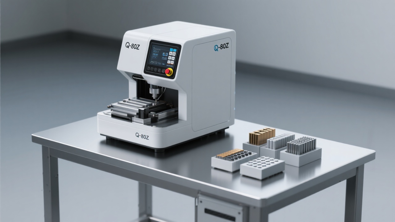
Case example: why labs often shortlist the Q-2 series
The Q-2 series is frequently evaluated for teaching and research settings because it aligns with how small labs actually work: compact footprint, manual control that feels predictable, and a cooling system designed to keep specimen temperature under control during longer cuts. In practice, labs typically focus on three design elements:
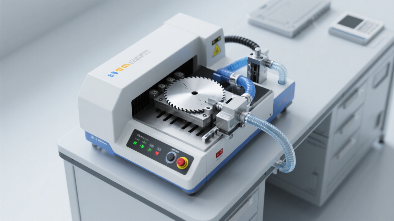
1) Structural layout that supports stable manual cutting
In manual cutting, the operator is the “feed system.” A stable mechanical feel—rigidity, smooth travel, and clear viewing—reduces sudden load spikes that can chip edges or overheat the cut. A compact unit with a well-contained chamber also prevents coolant mist and debris from turning the surrounding bench into a maintenance problem.
2) High-speed wheel + intelligent cooling as a paired system
Cutting performance is not only about speed; it is about energy management. A higher wheel speed can improve cutting efficiency, but only when coolant delivery is consistent and well-directed. Many research labs target a cutting condition where the specimen remains touch-safe shortly after the cut, and where discoloration on steels is minimal or absent—both are practical indicators that the cooling strategy is doing its job.
Expert note (metallography practice): “Avoiding heat tint and smearing at the cut stage reduces interpretive errors later. If the cut introduces a heat-affected layer, you may polish it away—but you can’t always recover true edge integrity.”
Commonly referenced in lab SOPs aligned with metallographic preparation principles (e.g., ASTM E3 guidance on avoiding preparation artifacts).
3) International compliance and documentation readiness
Research labs increasingly require traceability: equipment labels, electrical safety documentation, and test records. When a cutter offers clear conformity support (typical examples include CE compliance for applicable markets and documented factory testing), it reduces procurement friction—especially for public universities and institutes with strict asset acceptance workflows.
Parameter tips by material: a research-friendly starting point
In research cutting, “one setting fits all” is usually the fastest way to create artifacts. Below is a practical starting table many labs use to guide new operators. Exact settings depend on wheel type, specimen size, and fixturing; the goal is to keep the cut stable and cool while preserving edges.
| Material category | Typical risk | Suggested approach (manual cutting) | Cooling focus |
|---|---|---|---|
| Hardened steels / tool steels | Heat tint, tempering, burr formation | Use steady, moderate feed; avoid “forcing” through the last 10% of the cut | High flow, direct jet to cut zone; verify no discoloration |
| Aluminum / copper alloys | Smearing, wheel loading | Lighter pressure; dress/replace wheel when loading appears | Consistent coolant to reduce adhesion and keep wheel clean |
| Ceramics / cermets | Edge chipping, cracking | Very gentle feed; ensure rigid clamping and minimize vibration | Coolant stability to reduce thermal shock; avoid intermittent flow |
| Composites / layered samples | Delamination, pull-out | Support the cut; reduce pressure at interfaces; consider sacrificial backing | Maintain low temperature to protect resins/adhesives |
Field note: for small specimens, improving clamping and reducing feed variability often delivers more quality gain than increasing wheel speed.
Common mistakes that quietly ruin metallographic results
Compact manual cutters are forgiving, but not immune to user habits. In university labs, the same errors appear again and again:
Mistake: Treating coolant as optional
Low or misdirected coolant can create a thin heat-affected layer that looks like a “real” microstructural change. For teaching labs, a simple pre-cut checklist (coolant on, nozzle aligned, flow stable) prevents most issues.
Mistake: Forcing the last millimeters
Many chips and cracks happen at the end of the cut. Reducing pressure near breakthrough preserves edges—particularly for ceramics and composite interfaces.
Mistake: Ignoring wheel condition
A glazed or loaded wheel increases heat and wandering. As a rule of thumb, if cutting time doubles for the same material and thickness, inspect wheel loading and dressing needs.
Interactive prompt: Click to view the PDF operation manual (recommended for onboarding new lab users and standardizing SOPs).
Daily care that keeps performance stable (and audits painless)
Research labs often share one cutter across multiple projects. Preventive maintenance is less about “machine health” and more about result repeatability. A realistic routine many labs adopt:
| Task | Frequency | Why it matters | Time cost |
|---|---|---|---|
| Rinse chamber & wipe viewing window | Daily / after heavy use | Prevents debris buildup and improves visibility and safety | 3–6 min |
| Check coolant level and nozzle alignment | Before each session | Maintains consistent thermal control and cut quality | 1–2 min |
| Clean coolant tank / filter debris | Every 2–4 weeks | Reduces odor, clogging, and inconsistent coolant delivery | 15–25 min |
| Inspect wheel wear and mounting | Weekly | Prevents runout, overheating, and unexpected failure | 5–8 min |
For institutes with ISO-style documentation habits, logging coolant changes and wheel replacements often helps correlate microstructural anomalies with preparation conditions later.
A quick before/after snapshot from a shared university lab
In one shared materials lab (multi-user teaching + graduate research), the switch to a compact manual cutting workflow centered on better cooling consistency and clearer operator steps produced noticeable operational improvements within the first month:
Need a space-saving cutter that protects your microstructure?
Explore practical setup notes, recommended consumables, and SOP-ready checklists tailored for compact manual metallographic cutting—especially for Q-2 series evaluation in academic and research labs.
For more operating details, please visit our technical document center and download the latest PDF manual and maintenance log template.
Hardness_TesterHV-50A-1.png?x-oss-process=image/resize,h_800,m_lfit/format,webp)


